MAU 1006 2206-FIM
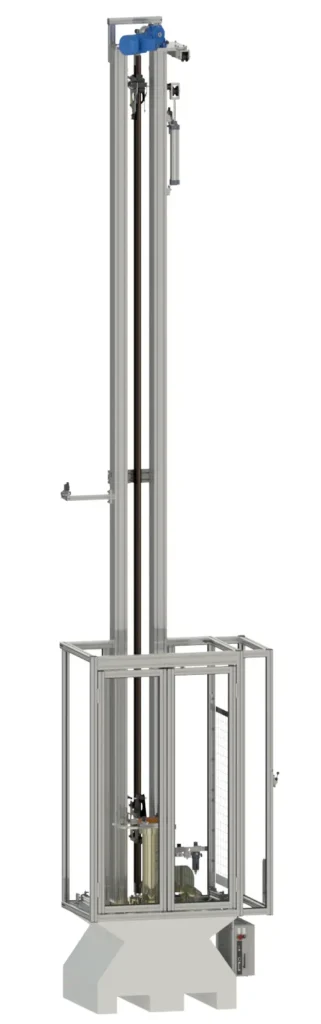
Monorail shock absorption testing system, compliant with ECE 22.06 and FIM standards. Utilizing the free-fall headform method with a 3.8 m drop height, the unit includes the base and electrical system. The structure features a double aluminium beam frame (120×80 mm), a two-part special drop carriage with 2 different helmet holder, and 3 anvils. Safety is ensured by a large protection cage with netting and automatic doors.
System Overview
- Application: Monorail shock absorption testing system utilizing the free-fall headform method.
- Compliance: Fully compliant with ECE 22.06 and FIM standards.
- Configuration: 3.8-meter vertical drop version featuring a double aluminium beam frame. Standard supply includes the structural ballast base, integrated electrical system, a two-part special drop carriage equipped with 2 different helmet holders, 3 impact anvils, and a large safety protection cage with netting and automated protective doors.
Technical Features:
- Guide Support Structure: Double-column layout manufactured from 120×80 mm ITEM aluminium profiles, integrated with a high-thickness (30 mm) lower foundation base and top structural support.
- Safety Enclosure: Integrated aluminium protection cage extending to a height of 2.2 m, constructed from 40×40 mm ITEM profiles and fitted with 3 mm thick impact-resistant transparent polycarbonate panels.
- Main Ballast Base: Hybrid steel and concrete structural box enclosure (dimensions: 850×745×550 mm) with a total mass of approximately 700 kg.
- Enclosure Safety Doors: Automated protective doors driven by twin pneumatic cylinders; frame built from aluminium profiles and fitted with transparent polycarbonate viewing panels.
- Monorail Guidance Assembly: High-hardness TMT Speed Rail™ aluminium monorail system, engineered with dedicated upper and lower rigid fixing interfaces.
- Leveling System: Adjustable foundation base equipped with 14 grub screws (Ø 14 mm) for absolute vertical axis alignment.
- Frame Anchoring: Secured directly to the structural ballast base via 6 high-tensile anchor bolts (Ø 16 mm thread).
- Deceleration Brake: Integrated pneumatic brake system for post-impact drop carriage deceleration, featuring adjustable clamping force regulated via a dedicated pressure gauge and pneumatic circuit.
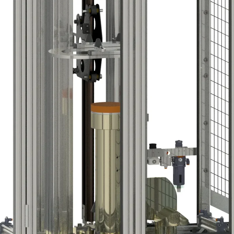
- Drop Carriage: Precision assembly manufactured from anodized Ergal 75 (high-strength aluminium alloy), equipped with four high-load ball bearings and adjustable low-friction nylon guide wheels.
- Specimen Fixture: Specialized helmet holder utilizing four soft conical rubber supports.
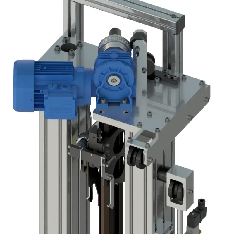
- Hoist System: Fully motorized winch assembly featuring an integrated belt drive, pulley, and electronic encoder, driven by automated variable-frequency inverter technology.
- Lift Carriage: Dedicated hoisting carriage featuring an automated pneumatic release system and limit-switch control via infrared photoelectric sensors.
- Catch Mechanism: Automated drop carriage latching and hooking system, operational during descent phases.
- Recovery Mechanism: Automated headform recovery system driven by a specialized pneumatic cylinder (Ø 50 mm, 250 mm stroke).
- Impact Anvils: Three standard impact anvils supplied: Kerbstone, Flat, and 45° Inclined. Components are fully interchangeable and easily mounted.
- Anvil Alignment: Anvil holder features an integrated laser alignment pointer to define exact impact point coordinates on the test specimen.
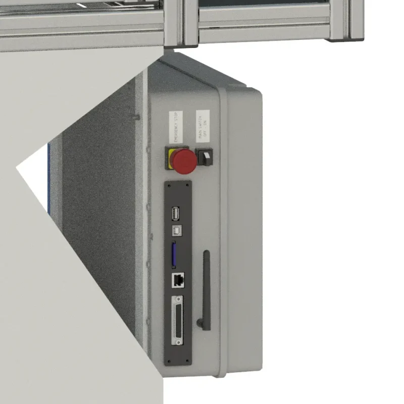
- Electrical Integration: Complete electrical distribution and routing networks fully concealed within the hollow channels of the structural frame columns.
- Pneumatics: Complete pneumatic regulation circuit equipped with an inline filter and analog pressure gauges.
- Velocity Measurement: High-frequency (10 kHz) laser photoelectric barrier device for precise pre-impact speed monitoring.
- Instrumentation System: Wireless transducer data acquisition configuration equipped with an integrated locking device.
- Surface Treatment: Mechanical and structural components finished with zinc-plating and anodizing treatments for enhanced corrosion resistance.
Technical Data & Installation Requirements
- Test Rig Weight: 230 kg (net weight, excluding the structural ballast base).
- Ballast Base Weight: 700 kg.
- Overall Footprint & Dimensions (W × D × H): 1140 × 920 × 5800 mm (compact frame configuration available on request).